top of page
Engineering Design and Analysis FEA Brake Rotor Analysis (Spring 2021)
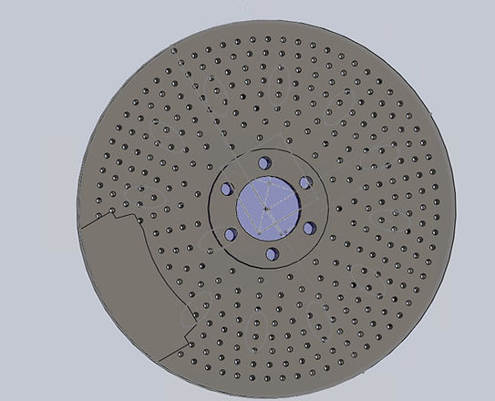
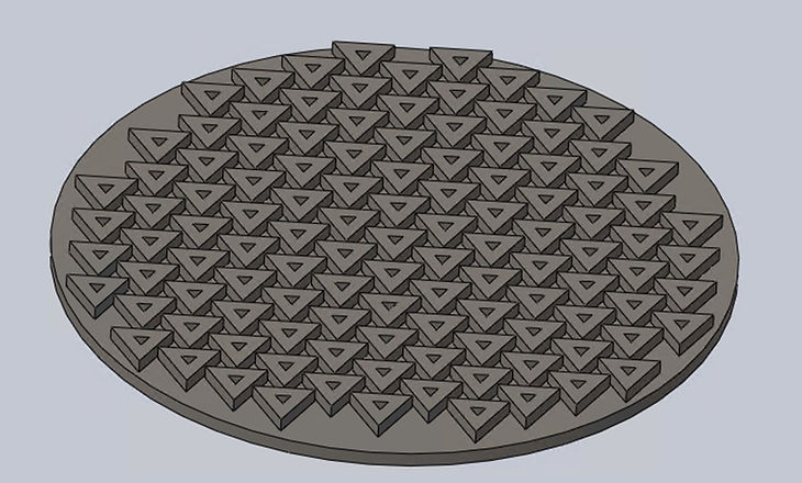
For my Engineering Design and Analysis course, I used given design specifications to create a brake rotor compatible with the given brake pad (AP Racing Radi-CAL 4 Piston Brake Caliper package).
FEA Brake Rotor Optimization: About

FEA Brake Rotor Optimization: Image
FEA Brake Rotor Optimization: Image
The brake rotor was created with SolidWorks and analyzed with the Simulation feature. It had four main elements: top disc, bottom disc, hub, and triangular array. The triangular array shown was created to provide structure and distribute the force applied by the brake pads while minimizing the weight of the rotor. 0.15 inch circular cuts were made to reduce weight while maintaining structure. More than 10 design iterations were completed to produce the strongest part possible.
FEA Brake Rotor Optimization: Text

FEA Brake Rotor Optimization: Image
FEA Brake Rotor Optimization: Image
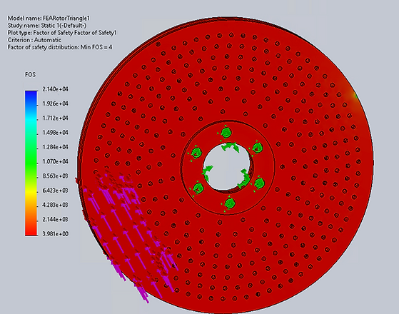
To model the forces on the brake rotor from the brake pads, the static simulation feature in SolidWorks was used. The inner diameter of the hub and 3/8 inch extruded holes in the top surface of the hub were used as fixed points. A sketch of the brake pad was added to the top and bottom surfaces of each rotor. 2,000 lbf were then applied parallel and 500 psi were applied perpendicular to the sketched brake pads to simulate their force on the rotor. The minimum Factor of Safety was 4. The FEA results can be seen below. The fixed points are highlighted in green, and the brake pad can be seen on the left, where the force arrows are located.
FEA Brake Rotor Optimization: Text
FEA Brake Rotor Optimization: Image
Looking at the figure above, there was not one particular area with a lower Factor of Safety than the rest of the rotor that may be the source of failure and low efficiency. This may be a result of the uniform thickness of most of the rotor components, where the thickness of the hub, triangular lattice, and discs fell between 0.23-0.3 inches. The 0.15 inch extruded circular cuts through the part may have weakened the rotor, as they were also extruded through the triangular support lattice. The small blue-green area on the right edge of the rotor above has a higher Factor of Safety than rest of the rotor. This indicates that there was less stress on the rotor farther from the brake pads.
FEA Brake Rotor Optimization: Text

FEA Brake Rotor Optimization: Image
To address the points discussed above, more support could be added closer to where the stress is applied. For instance, the triangular lattice could be designed with a larger difference between the inner and outer dimensions of the triangles closer to the brake pads so that the extruded support would be wider closer to the most stress. The rotors could also be designed so that the 0.15 inch extruded circles do not cut through the triangular lattice.
FEA Brake Rotor Optimization: Text
bottom of page