top of page
Mechanical Systems Design Gas Pressure Vessel (Fall 2021)
In my Mechanical Systems Design course, I worked with four other engineers to design and machine a pressure vessel for a laboratory environment.
For this project, I was responsible for creating the CAD of our vessel, running the FEA to understand stress concentrations, completing hand calculations to find stress on the vessel and bolts, and assisting with machining.
To see the complete design process and calculations, see our full report.
Gas Pressure Vessel: About

Gas Pressure Vessel: Image
The pressure vessel was designed to hold 50 ccs of liquid at 750 psig. The main body of the pressure vessel is cylindrical 6061 aluminum with a cap. 6061 aluminum was selected for its strength, machinability, low-cost, and corrosion resistance. The cylinder has an O-ring groove for a face seal with a size 24 O-ring and is connected to the cap with four 10-32 screws and washers. A 1⁄4” NPT fitting is threaded into the center of the cap with Teflon tape. The materials for the pressure vessel cost a total of $49.69, and the machining costs for the vessel are approximately $200. With an internal pressure of 750 psig, the results of the FEA yielded a factor of safety of 14, and the pressure vessel has been proven to be effective for its intended purpose.
Gas Pressure Vessel: Text
For this project, I performed stress calculations on the vessel from the fluid. Stress from internal and external pressure on the vessel was found by treating it as a thick walled cylindrical pressure vessel. This analysis was chosen because the ratio of wall thickness to radius (0.55” to 1”) is greater than 0.1, so the system cannot be approximated as a thin-walled vessel. For thick-walled vessel analysis from Shigley’s:
Gas Pressure Vessel: Text

Gas Pressure Vessel: Image
To combine the tangential, radial, and longitudinal stresses on the vessel (Eqns 1-3) from internal and external pressure into one value that could be compared to yield strength of the material selected, Distortion-Energy theory was used. This approach was selected, as it is the most widely used and preferred theory for ductile materials.1 Using Distortion-Energy theory, von Mises stress was found from Shigley’s using the tangential, radial, and longitudinal stresses shown above. The von Mises stress was calculated as 1,597.07 psi . For Aluminum 6061, the yield strength is 35,000 psi. Comparing the von Mises stress to the yield strength gives a Factor of Safety of 21.9.
Gas Pressure Vessel: Text
To ensure that the preload of 1,837.5 lbf was applied to the bolts, I found the torque we needed to apply to each bolt during assembly. This was done with Shigley’s Eqn 8-27:
𝑇𝑜𝑟𝑞𝑢𝑒=𝑇=𝑘*𝐹𝑖*𝑑 (16)1
From Table 8-15, k=0.3 (for a non-plated, black finish)1
Thus, the necessary torque was calculated as 104.74 lbf*in .
Gas Pressure Vessel: Text
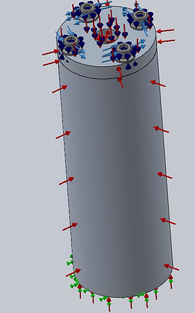
I conducted finite element analysis (FEA) to ensure the stress concentrations at the flat ends of the cavity in the vessel as well as around the outlet of the NPT would not cause the vessel to fail. To complete the FEA, the two main parts of the design-- the cap and cylindrical chamber were imported into a Solidworks assembly as Aluminum 6061-T4. Then, the bolts and washers were imported from McMaster. A static simulation was performed, where the washers were rigidly connected to the top face of the cap, and the bottom faces of the heads of the bolts were rigidly connected to the top faces of the washers. A torque of 104.74 lbf*in was applied to each of the 4 bolts. The internal pressure was set at 750 psi, and the external pressure was set at 14.7 psi.
Gas Pressure Vessel: Text
FEA Setup
Gas Pressure Vessel: Image
von Mises Stress

Gas Pressure Vessel: Image
Factor of Safety

Gas Pressure Vessel: Image
From this analysis, the maximum von Mises stress was 2,334 psi, and the minimum factor of safety was 14. This is a higher stress than that found with Distortion-Energy theory, which yielded a von Mises stress of 1,597.07 psi, and minimum factor of safety of 21.9. Looking at the figures above, the highest stress concentrations are near the NPT as well as where the curved interior wall of the vessel meets the flat faces at the end of the cavity and bottom face of the cap, as predicted by the team. Although the stresses here are higher than predicted, the FOS is still very high, and the vessel will not fail from pressure or the bolts.
Gas Pressure Vessel: Text
Machining of the designed pressure vessel took place in the Pratt Machine Shop using a Sharp 1640 Lathe, Centroid CNC Mill, Centroid CNC Lathe, and an ATrump Manual Mill. The first step was to measure the piece of 6061 aluminum cylindrical stock to determine its initial dimensions (length and outer diameter). Next, the part was inserted into the chuck of the lathe, and one side was faced off to reach the desired length of 5.8125” (5.5” chamber length + 0.3125” cap thickness). While this manufacturing choice did not largely affect the final outcome of the part, in retrospect, an additional step of facing off the other side of the stock would also be ideal in order to ensure that the face was perfectly flat.
A small hole was drilled in the center of faced off end of the cylinder to use the tailstock to support the piece for the
next operation. The outside face of the cylinder was then smoothed down by a couple thousandths of an inch to ensure that part was entirely round. The part was then transferred to the manual mill and positioned using a vice and V-block. After edge finding with a dial indicator, a center drill was used to drill the four bolt holes at a radius of 0.785 inches. These holes were then drilled down to a depth of 1.25 inches to ensure they were long enough for the bolts to pass through the cap and thread into the chamber. Next, the hole for the 1⁄4” NPT fitting was drilled into the center of the piece, starting with a center drill and moving up in size until reaching the 7/16 bit to a depth of 1 inch. This center hole was tapped to thread it to a 1⁄4” NPT standard. Next, the part was inserted back into the lathe in order to cut the 0.3125” cap off the end of the part. The four 10-32 screw holes in the cap were increased to a number 9 body drill bit in order to create clearance for the screws. These holes were then countersunk and deburred. The cap was finished by inserting the 1⁄4” NPT fitting after wrapping its threads with teflon tape. The hollow center of chamber piece was then bored out with a 7⁄8” drill bit in the tailstock to a depth of 5” to hold the fluid that would be pumped into the pressure vessel. A boring bar was used to increase the inner diameter of the chamber to the designed 0.9”. It was at this stage that the other end of the chamber was faced off. Next, the screw holes in the chamber piece were tapped with a 10-32 tap. The final step was to use the CNC Centroid mill to mill a programmed groove for a size 24 o-ring into the face of the chamber. The groove was smoothed down by hand with sandpaper to reduce the chance of surface roughness damaging the o-ring.
Gas Pressure Vessel: Text
bottom of page